This past weekend I went off to my buddy Scott’s house. One of Scott’s newer toys is his CNC milling machine…which is about to become very handy. Rummaging around in his collection of off-cuts, we found some 7075 Aluminium that was sized appropriately. Just gotta remove the bits that aren’t front VW hub :P Every time I’m over here, I think to myself “gee I need a bigger lathe”. With Scotts you can take 1/2” cuts off an aluminum chunk of this size. That’s a full inch off the diameter in one pass!
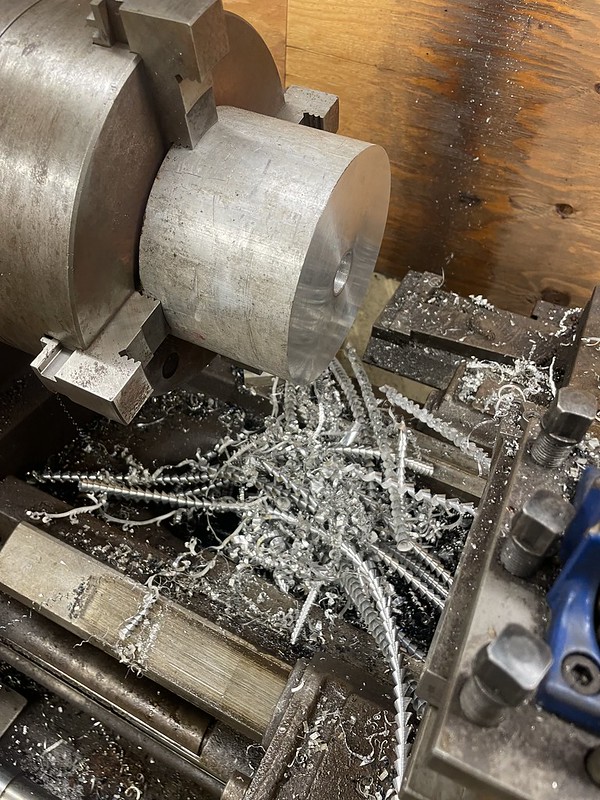
I prepped the stock, while Scott turned my 3D model into G-Code and movements on the CNC machine.

For those of you who aren’t machinists, who are curious how this is done…here we go.
First we cut a set of aluminum jaws for the vice, and machined a half circle into each. They are machined to match the diameter of the finished hub’s backside outer diameter. On the lathe, I prepped the aluminium piece to have an outside diameter on the
front side that matched this dimension. Now we can hold the piece in the vice, and machine the backside.

The part is then flipped, measured to confirm it’s zero’d perfectly, and the front side is machined.

Most of the dimensions are machined right away to the finished size, with the exception of the areas that the bearing races are set to.
These are first machined with an extra 0.020” left in their diameter. A measurement is taken, and then they are machined again an additional 0.010”. Measuring again, we can now confirm
exactly how much was taken off.
The amount removed can can change by a few thousands simply due to tool flex, cutter wear, or other factors. Since we told the machine “take 0.010 off”, and we measured 0.095 off, we can now tell the machine to take 0.015 off and the bearing areas should be perfect.
Following the machining, the bearings are put in and run-out is checked. Lastly it was back onto the lathe to chamfer any sharp transitions…mostly because we were too lazy to program the tool changes and radii into the CNC machine (since we could quickly do it on the lathe).


Scott had a nice chunk of 1” thick aluminium hanging out from his truck project, so we also put my brake calliper mounts through the computer. I gotta say, it’s a tonne of fun watching something you designed slowly appear out of aluminium. For the brake mounts Scott programmed the G-code, but made me do the setup and run the machine. Always good to learn new skills! The goal is to eventually get me to the point where I can just come over and use the CNC machine, without taking up his whole weekend on my projects.


Back home in the shop, and it all fits as though I actually know what I’m doing. Hmph.
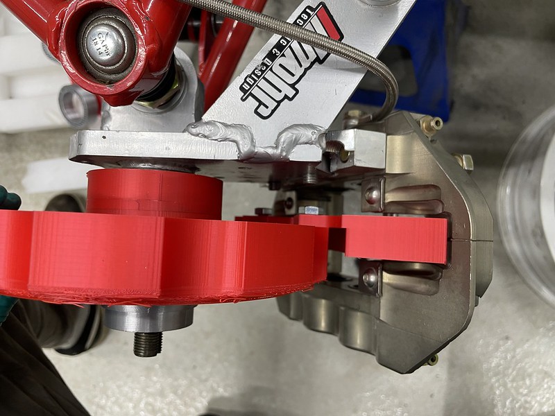
With the fronts done, I started working on the rear setup. I figured out that the Imohr brake setup is off of a 2010 VW Golf (or similar) so grabbed a caliper from my local parts store. It’s a bit awkward to mount on the suspension, and the parking brake cable is definitely going to be an issue. But, they are freaking light.


Despite the awkward angle of the mounting surface, and the difficulty in measuring it all out, I managed to get it spot on in two 3D printed tries. Not too shabby considering. But, sitting back expecting some sense of accomplishment and excitement for the next part…I couldn’t help but feel like it’s just too wimpy.

Oh gee…it’s like a honda civic with the mini drums still in the back. Or the fast and furious days when they sold the red-anodized rotors people would bolt between drum and wheel. Hmm, surely we can come up with something a little more robust that still has a parking brake feature?
I hit the couch for some surfing…and bad ideas started to pop into my head.


I mean, I do own a matching set of front and rears.
…but it creates a parking brake problem.
…BUT, the balance front to rear would be pretty easy on the hydraulic side.
I mean, we could just
see how they fit?
Three episodes later, and the mount for testing was out of the 3D printer.


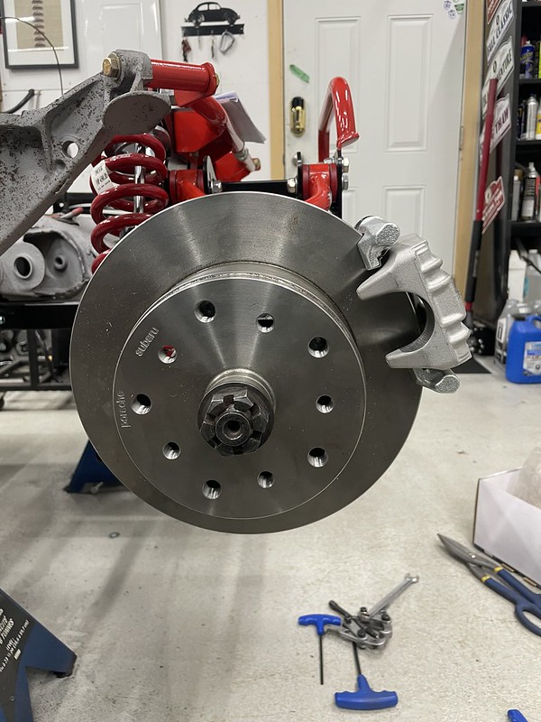
Yeah…remember that whole post about unsprung weight, not getting enough heat into the brakes, and how silly big brake setups are on beetles? Oops. I guess I’m all in now. Time to sort out the rears!

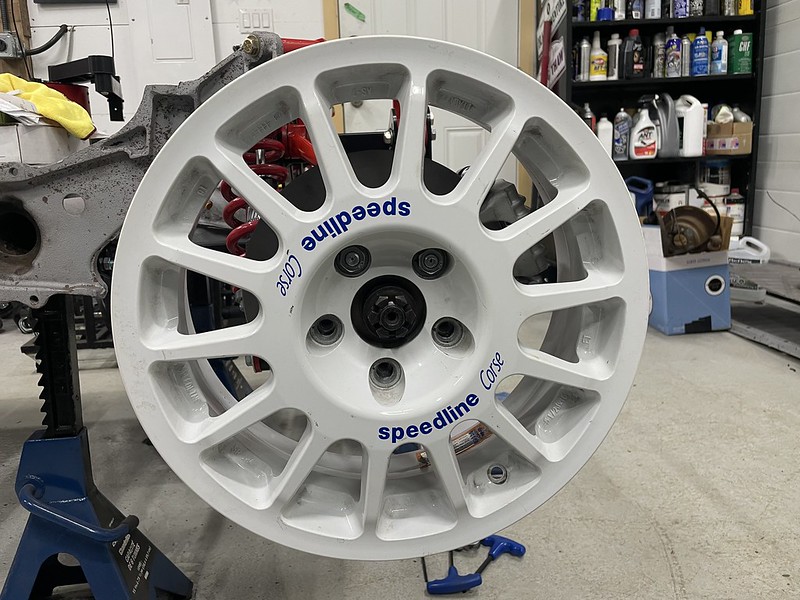
I’ve got these splined hubs from SubaruGears that allow for using the Subaru rear drum parking brake setup, and (in this case) a Subaru Impreza disc and caliper. They increase the rear track by 12.5mm a side, which adds some complications.
If I want to use the white Speedline wheels, with the offset they have, I’ll need to cut the hubs down by 12.5mm and lose the ability to use the Subaru drum-parking brake. BUT, doing so also opens up options for a wide variety of rotors. My second option, if I want to source all the STI rear brake stuff, is to split up my sets of Speedline wheels, run the gold offset on the rear, and the white offset on the front. Not sure what that will mean for the Rally Bug, where the gold wheels are supposed to end up. Or I find a different mechanical parking brake option and run a second set of calipers. That’s option 3.

Time to spend some time thinking…