
|
|
|
|
#1
 December 13th 2007, 22:18
|
||||
|
||||
|
Relocating Oil Breather
Slide 42- Relocating Oil Breather
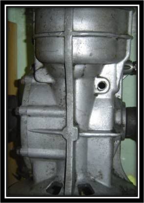 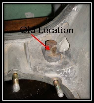 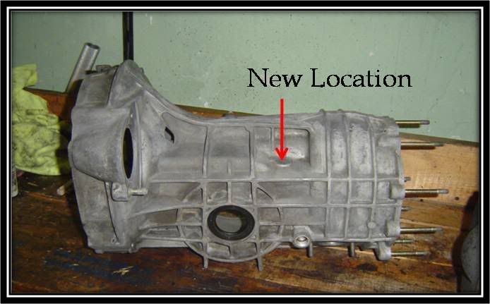 When using a 914 box it is necessary to relocate the oil breather tube to the same location as it would be found on a 901 box Bottom picture shows where the new location will be on the 914 box Slide 43- Relocating Oil Breather (Cont) 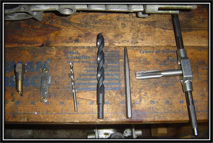 Some of the tools you will need to accomplish this task: Oil Breather Thread Pitch gauge Small drill bit for pilot hole Large bit Punch Tap and Handle Note: Remember your safety equipment (eye protection) Slide 44- Relocating Oil Breather (Cont) 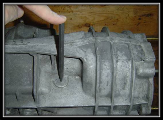 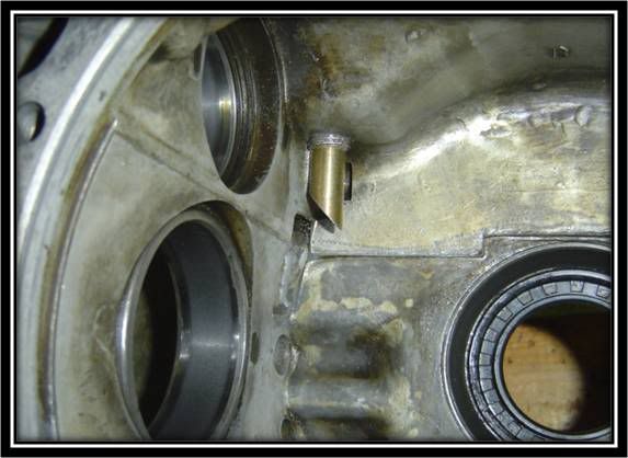 Use a Punch to mark the new location of oil breather tube Ensure new location of tube clears case internals Slide 45- Relocating Oil Breather (Cont) 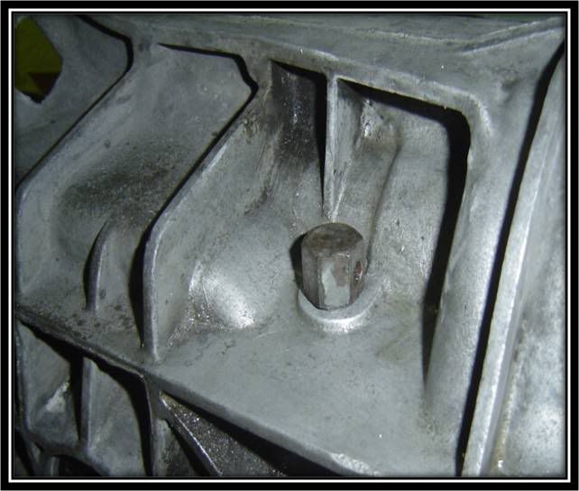 Use a small drill to create pilot hole Use appropriate large drill to open up hole to correct size for tapping Use gauge to verify correct tap size Using cutting oil, and tap with handle cut new threads onto case Slide 46- Relocating Oil Breather (Cont) 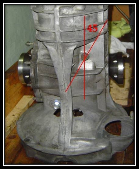 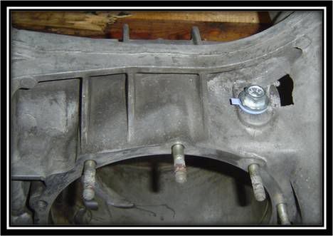 Lastly fit breather into new location. Breather should have approximately 45 degrees offset Plug old hole with automotive plug Oil Plug can be used
__________________
Alex Olaverri Sales Associate for Bug@5-Speed (US) Email: Bugat5speed@yahoo.com Tele: 973 204-5463 
|
|
#2
December 13th 2007, 22:22
|
||||
|
||||
|
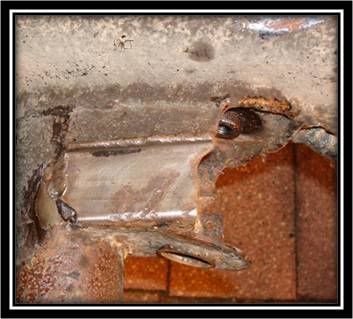
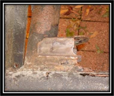
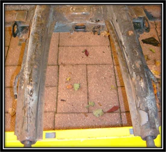
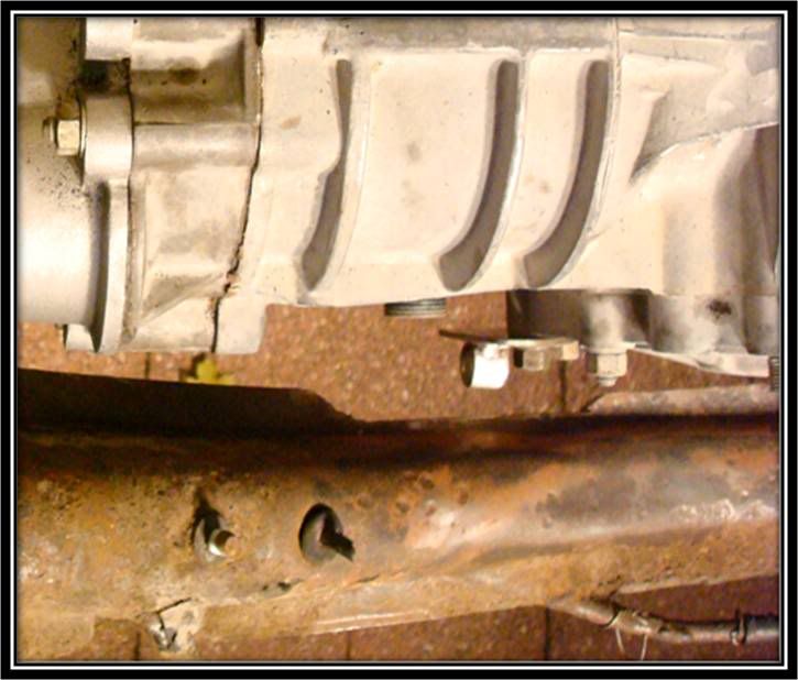
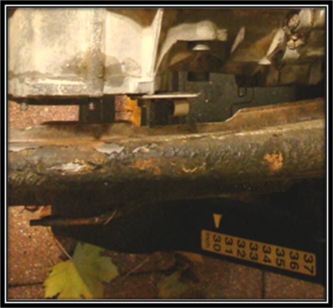
Type I IRS Chassis Prep
Slide 46 Type I IRS Chassis Prep
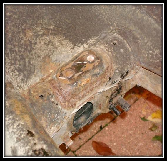 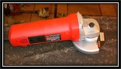 Installing the Bug@5-Speed Conversion kit can be done with body on or off. When installing the kit, it will be necessary to remove the old beetle transmission mounts as shown in the top picture A grinder and some eye protection make quick work of the transmission mount bolts This is what chassis should look like after bolts are ground off and surface made flush That's it for today.. Tomorrow the rest of chassis prep Enjoy and comments always welcome. Alex
__________________
Alex Olaverri Sales Associate for Bug@5-Speed (US) Email: Bugat5speed@yahoo.com Tele: 973 204-5463
|
|
#3
December 16th 2007, 16:26
|
||||
|
||||
|
Lots of good info here... but let me add a $$$$ tip: Use Loctite on all bolts and nuts on initial thighting! or they wil vibrate loose.
Cant wait to pick up my parts and start the conversion! Going to visit Martin in January. Last edited by Turbo Haraune2; December 16th 2007 at 16:28.
|
|
#4
December 17th 2007, 19:05
|
||||
|
||||
|
Thanks for the reminder.. Very true..
You'll have fun over at Martin's..
__________________
Alex Olaverri Sales Associate for Bug@5-Speed (US) Email: Bugat5speed@yahoo.com Tele: 973 204-5463
|
|
#5
December 17th 2007, 19:13
|
||||
|
||||
|
Slide 49- Type I IRS Chassis Prep
   With 30+ years of grim and dirt, now is a good time to wire-wheel and clean the bottom of the IRS mounts Also clean the flat section of the frame horns This will help with test fitting the gearbox and when you need to identify areas that need to be clearance Slide 50- Type I IRS Chassis Prep 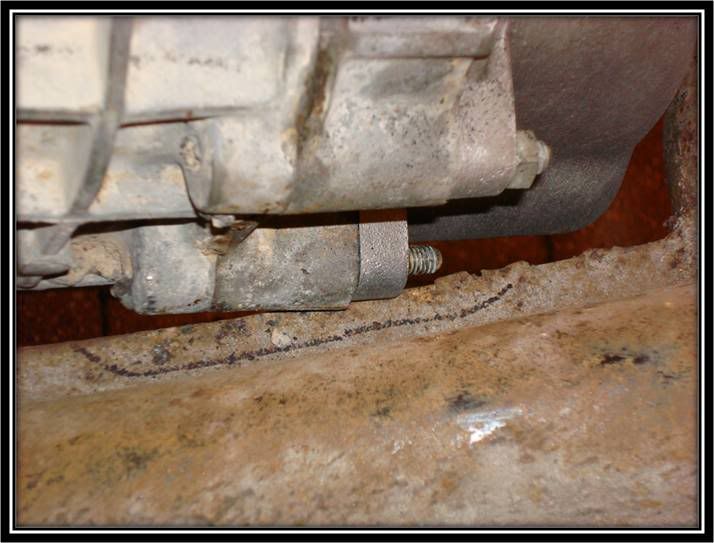 One of the first areas that you will notice that needs to be marked for clearance is the right hand side of the nosecone/intermediate plate (looking from top of chassis) Slide 51- Type I IRS Chassis Prep 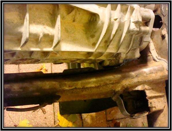 Shown here is the clearance for the reverse gear switch Slide 52- Type I IRS Chassis Prep 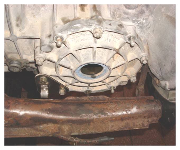  Shown is the clearance for the Clutch Cable Adapter Plate and for the TOB Fork
__________________
Alex Olaverri Sales Associate for Bug@5-Speed (US) Email: Bugat5speed@yahoo.com Tele: 973 204-5463
|
|
#6
December 17th 2007, 19:22
|
||||
|
||||
|
Slide 53- Type I IRS Chassis Prep
  Few more pictures of clearance for Clutch Cable Adaptor Plate Slide 54- Type I IRS Chassis Prep  Once all the clearances have been cut into the frame horns, this is what your chassis should look like. 1-Clearance for the intermediate plate 2-Clearance for shifter cable adapter plate & Bowden tube 3-Clearance for TOB fork 4-Clearance for reverse gear switch (optional) Slide 55- Type I IRS Chassis Prep 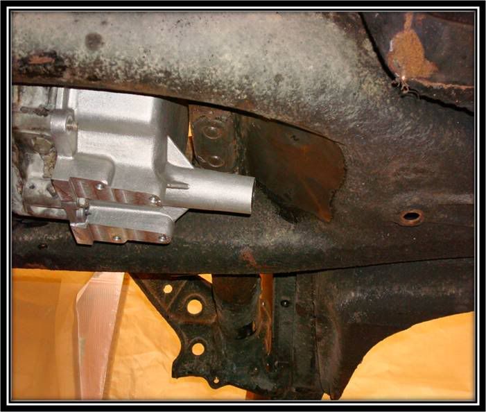 Gearbox is situated between frame horns to begin marking area to be cut for the inner shift-rod that will enter tunnel in the new location Slide 56- Type I IRS Chassis Prep  Using a wire wheel, area to be cut was cleaned to enable marking of the necessary patter for the shifter coupling to fit through the tunnel: Porsche Shifter Coupling requires hole cut to 60mm x 120m If using a VW Shifter Coupling it requires hole cut to 70mm x 120mm, due to larger size Slide 57- Type I IRS Chassis Prep 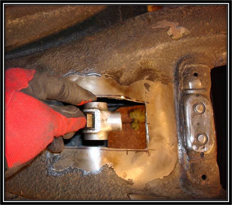 Once the hole is cut this is where the shift rod will enter tunnel. Notice the Porsche Shifter coupling Slide 58- Type I IRS Chassis Prep 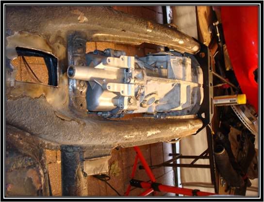 With shifter coupling hole cut, its now time to center our attention onto the front traverse, and the IRS mounts which serve as the mounting point for the gearbox Slide 59- Type I IRS Chassis Prep  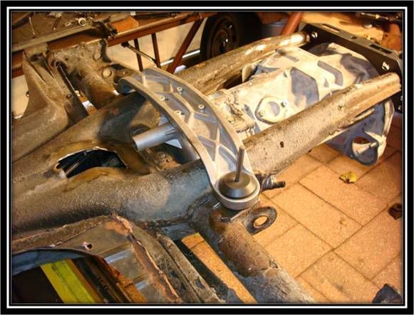 With the gearbox installed with the front and rear traverse, we will mark the location for the bolts to attach to the IRS mounts.
__________________
Alex Olaverri Sales Associate for Bug@5-Speed (US) Email: Bugat5speed@yahoo.com Tele: 973 204-5463
|
 |
| Currently Active Users Viewing This Thread: 1 (0 members and 1 guests) | |
|
|


 Hybrid Mode
